IEC 61131-3 programming languages
IEC 61131-3 Programming Languages
With so many programmable logic controller (PLC) programming languages and standards from which to choose, what is the right choice for automation and controls applications?
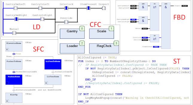
IEC 61131-3: Programming languages: LD, SFC, FBD, CFC and ST
- Ladder Diagram remains popular because of its graphical nature.
- Sequential Function Chart is a graphical language great for expressing state machines and appeals to the graphical nature of engineers.
Programming language choices for programmable logic controllers (PLCs) are many. It is said the great thing about standards is there are so many to choose from! While this is meant as sarcasm, in the case of IEC 61131-3 Programming Languages, it is an advantage to have several language standards from which to choose.

Figure 1: IEC61131-3 Programming Languages offers languages suited to specific needs.
With IEC 61131-3 programming languages, PLC programming and maintenance are enhanced when the strengths of all the languages are used.
What is Ladder diagram (LD) programming?
Ladder diagram programming, or LD, traces its history back some 100 years to relay ladder logic (RLL), which was created to describe systems of electrical components such as relays, timers and motors. In the early days of automation, when PLCs were replacing relays and timers, it made perfect sense to create a programming language familiar to the user base and similar to the tool it was replacing. Unfortunately, as controllers became more capable and evolved past relays and timers, the original LD language was pressed into services it was never intended for and was poorly suited.
This situation was exacerbated by the slow pace at which PLC vendors provided new languages better suited to PLC and programmable automation controllers (PAC) applications. This was particularly true with controllers originating in North America, which explains the global differences in the enduring popularity of LD.

Figure 3: Diagram compares languages for complex Boolean logic as implemented in Codesys
Strengths of LD programming
The strength of LD and the key to its enduring popularity is its graphical nature. Of all the generalizations one can say about engineers (as is often illustrated in your favorite Dilbert cartoon), it is safe to say engineers tend to be graphically oriented. (Who among us can effectively communicate without paper and pencil, or a white board?) Early on, most LD programming alternatives were text-based languages that did not resonate with engineers’ graphical nature. This led to further reluctance to move on from LD. Fortunately, that situation is changing.
LD remains a great language for which it was originally intended – complex Boolean logic. Staying within this realm, LD logic is simple to design and simple to debug. Figure 3 illustrates this point by showing the same Boolean logic in several IEC 61131-3 languages. Say we are expecting “Inspect” to be TRUE. How easy is it to determine why the result is not as expected? In LD, the answer is quickly determined by observing where the path of solid blue contacts is interrupted (GantryIsRight is not TRUE). In CFC and FBD, the issue also can be determined by observing the progress of the blue path, but it does require mentally evaluating the ANDs and ORs. Evaluating the issue in text is a challenge.
What is sequential function chart (SFC) programming?
Sequential function chart (SFC) is a graphical language great for expressing state machines, and, like LD, appeals to the graphical nature of engineers. To provide better context, this programming language discussion will be broken into two parts:
1) State machines in general, and
2) The language to implement a state machine.
What are state machines?
State machines date back many years, but only more recently have been applied to industrial programming. State machines are a very powerful method for expressing a system whose behavior depends on past history, such as any logic with:
1) Set coils or reset coils
2) Seal-in logic (Boolean feedback)
3) Internal flags that are set by the code to affect the behavior of the code on future scans.
In reality, even the simple TON On-Timer and R-Trig one-shot are state machines. Their next behaviors depend on previous inputs and behaviors as shown in Figure 4. (Has IN gone true? Has the target time been reached?)

Figure 4: Even the common TON timer and R-Trig one-shot are state machines. They are shown here implemented in Codesys SFC.
State machines offer many benefits over other coding techniques:
1) They’re easy to design because it clearly describes the states a system can be in, how the system transitions between those states and the actions the system should take while in those states.
2) During runtime, it is easy to see exactly what state a system is in, what it is doing in that state, and what will cause it to move to the next state (or why it isn’t moving to the next state if something has gone wrong in the process).
3) It promotes well-conceived and well-organized designs. It assures all possible eventualities have been handled (thus eliminating the chance of being called in the middle of the night to fix code that didn’t properly address an unusual condition).
4) Easy to determine that every possible eventuality has been properly tested. Just print out the SFC and cross off each state and transition as it is exercised. When everything is crossed off, testing is complete (and the programmer’s confidence level is 100%).
State machines can be implemented in different ways.
How to implement a state machine
While state machines can be implemented in almost any language, they require a specific coding technique, which consists of steps, transitions, branches/jumps, and actions.
Steps describe the states of which a system can reside; Transitions indicate when a system should move from one step to the next; branches and jumps indicate what that next step should be; and actions specify what operation should be performed while in that step (or entering or exiting that step).
Due to its graphical nature and specialization for the job, SFC is the most natural choice of language for state machines as shown in Figure 5.

Figure 5: Diagram shows programming components of a sequential function chart (SFC).
Figure 6 shows an example of a state machine for a loading system as displayed in the online mode where the current states are displayed in blue. Notice this example has three simultaneous parallel branches that run independently of each other. Also notice how simple it is to determine the current state of the system, what the system is doing in the current state, what the next states are, and what conditions are required to move on to the next states.

Figure 6: Example shows a sequential function chart (SFC) with simultaneous branches as implemented in Codesys. Courtesy: ControlSphere Engineering
For system requiring unusual complexity or flexibility, state machines also can be implemented in text-based languages as shown in Figure 7. For organizations locked into using LD, state machines can even be implemented in LD by using a coil for each state, transition logic to energize/deenergize each coil to move the system from one state to the next, and separate logic that uses state-coils to implement the actions.

Figure 7: State Machine implemented in Structured Text with enumerated steps.
Some vendors also provide an implementation of unified modeling language (UML) state diagrams as a more powerful and flexible alternative to SFC, but this comes at the price of a longer learning curve and limited acceptance in the industrial controls community.
When it comes to state machines, the choice of language is secondary to the choice of technique within the language. In SFC, the language forces the use of the state machine technique. In other languages, it’s up to the discipline of the engineer to use the proper technique. If the functionality depends on previous history, it’s a state machine. For optimal code, implement it as such.
[A related Control Engineering article explains “UML use cases, sequence diagrams: easily converted into executable code.”]
- Function block diagram (FBD) is a graphical language which appeals to engineers’ affinity for graphical languages.
- Continuous function chart (CFC) programming, a super-set of FBD, is a similar but more flexible extension to IEC 61131-3.
- Structured text (ST) is based on the PASCAL programming language and has enough similarities to VB to make use of the more widely available VB tutorials.
Function block diagram (FBD) and continuous function chart (CFC)
Function Block Diagram (FBD) is a graphical language which appeals to engineers’ affinity for graphical information. The Codesys integrated development environment (IDE), from Codesys GmbH (previously called 3S-Smart Software Solutions), offers two flavors of FBD, the traditional IEC 61131-3 FBD and the similar but more flexible continuous function chart (CFC) which is not formally part of IEC 61131-3. CFC is a super-set of FBD and has two areas of strength:
- Block-based functional programming (performing Boolean and mathematical operations)
- Hierarchical designs (calling other functions and function blocks).

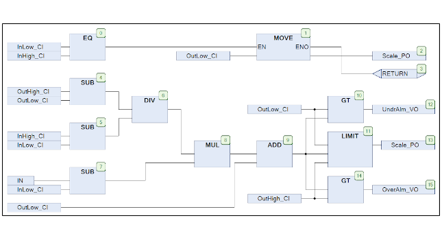
Block-based programming with CFC
Block-based designs consist of assemblies of pre-defined functionality which are wired together to carryout Boolean logic, mathematical calculations, or a combination of the two as shown in Figure 1. CFC block programming is excellent when the outputs are strictly a function of the current inputs (in other words, when there are no state variables such as Boolean feedback, set/reset coils, or flags). When there is a combination of state-less and state-based functionality, use a combination of CFC and SFC.
Because connectivity is represented with lines between the function blocks, it is easy to understand the flow of information and how the information is modified along its path. If the functionality begins to become complex, it should be split into smaller, more manageable sub-blocks as described in hierarchical designs below. If there are a significant number of connections between blocks, the lines can be consolidated into pins that are declared as a data structure type as shown in Figure 2.

Figure 2: Structure pins enhance readability of diagrams by reducing unnecessary detail and clutter.
Three advantages of structured pins
Structure pins have three advantages:
- They remove unnecessary detail from this level of the design hierarchy so that the forest isn’t lost in the trees (to paraphrase the saying).
- Keeps the block size small so that the overall flow of information can be viewed on one page
- Allows information to flow upstream and downstream (to further reduce the unnecessary detail).
Hierarchical designs with CFC
Hierarchical design is the practice of creating a design from building blocks, which are built from simpler building block, which are built from simpler building blocks and so on. Small building blocks have many advantages over the traditional large flat designs, including being easier to:
- Specify
- Create
- Test and perfect
- Understand and maintain
- Be much more likely to be reused.
The building block technique is easier to design and understand because it enables and encourages the practice of maintaining a consistent level of detail at each level of the hierarchy. In this way, upper levels of the design are not cluttered with confusing and unnecessary detail that is important at the lower levels of the design. The analogy is an automobile engine which has a starter, which has an armature, which is wound with copper wire, which is extruded from copper, which is mined throughout the world. The automobile designer doesn’t need to be an expert or be concerned with how the copper in the engine is mined. This level of detail is left to the lowest levels of the design, where that detail is important. Hierarchical CFC designs should be designed with a consistent level of detail on each level of the hierarchy.
Two downfalls of using LD as a building-block language
This reveals the downfall of the traditional method of using LD as a building-block language. Specifically:
- The low density of information requires LD designs to be spread-out over dozens of pages, making it difficult or impossible to see and understand the big picture.
- High-level details and low-level details are intermingled on the same level leading to clutter, which makes the design difficult to understand and maintain.
Hierarchical design in CFC using structure-pins solves both of these problems, while maintaining the graphical nature of LD. It’s a no-compromise solution with the best of both worlds.

Figure 3: Hierarchical design is implemented here in Continuous Function Chart (CFC) graphical programming.
Benefits of using CFC and hierarchical design
Hierarchical design is a key feature of object-oriented industrial programming (OOIP). Figure 3 shows an OOIP design of a control system for a racing sailboat. The top-level of the design shows the boat control consists of inputs and outputs (I/O), services, winches, cylinders, and hydraulics. Double-clicking any of those blocks reveals the next level of detail such as the overview of the cylinders and the hydraulic system. Further double-clicking on any blocks in those reveal progressively further levels of details, each implemented in the best language for the job. Notice the careful attention to keeping the CFCs one page and of consistent levels of detail so the functionality is easily understood at each level. These objects are then configured with a .CSV file as shown in the OOIP article and video referenced at the end of this article.
With the ability to place and configure user-defined blocks, CFC programming begins to closely resemble programming/configuring for a distributed control system (DCS), except with IEC 61131-3, the programmer is in control of the underlying blocks. If a block needs a minor enhancement, the programmer has the power to do this without the expense and time required to involve the DCS vendor.
A complete hierarchical PLC design can be thought of as a tree with hierarchical CFC making up the trunk and branches (the block diagram); and block-based CFC, SFC, LD, and ST filling in the detailed functional design at the leaves of the tree. Together, the IEC61131-3 language forms a team which is more powerful than any of its individual parts.
What operations should be programmed with structured text?
While LD, SFC, and FBD/CFC are great tools for their purposes, there are some operations that do not lend themselves to graphical languages.
Some operations that favor use of ST programming include:
- Iterative operations such as For, While, and Repeat
- Complex conditionals and selections such as IF-THEN, and CASE
- Bit manipulations such as bitwise-AND, Shift, Rotate
- Text string manipulation
- State machines with unusual requirements or complexity
- Pure object-oriented programming (calling methods, setting properties, etc.)
There are many good tutorials available for engineers transitioning from other text-based languages to ST. A Visual Basic tutorial is a good starting point for those completely new to text-based languages. While structured text is based on the Pascal programming language, it has enough similarities to VB to make use of the more widely available VB tutorials.


Comments
Post a Comment